UML with Enterprise Architect
Introduction to UML
UML (Unified Modelling Language) is a standardised graphical language used for visualising, specifying, constructing, and documenting (software) systems. It offers a set of standard diagram types to represent complex issues, processes, and systems in a clear and comprehensible manner.
UML is neither a methodology nor a process but acts as a ‘dictionary’ of symbols, each with a defined meaning. It provides diagram types for object-oriented analysis, design, and programming, facilitating a seamless transition from system requirements to final implementation. By depicting the structure and behaviour of a system, UML helps identify areas for optimisation.

UML Diagrams
Diagrams play a crucial role in UML. Discover all the available diagram types at a glance.

Documentation
A key element of UML is the ability to use diagrams as part of the project documentation. These can be reflected in a wide variety of documents, for example use case diagrams can be included in the requirements definition to describe the functional requirements. Class or component diagrams can be used as software architecture in the design document. In principle, UML diagrams can be used in practically any technical documentation (e.g. test plans) but can also become part of the user manual.
Advantages of UML
Improving collaboration
Cutting costs during the implementation phase
Huge time savings thanks to roundtrip engineering
Also suitable for organisational projects
Using UML as a ‘common language’ fosters better collaboration among project managers, business analysts, software/hardware architects, designers, and developers. It helps teams better understand systems, uncover opportunities for simplification or reuse, and identify potential risks. By addressing errors early in a project, costs during implementation are reduced. Round-trip engineering also provides substantial time savings, especially for developers.
Although UML was originally developed for modelling software systems, it can in principle also be used for organisational projects. The ability to visualise processes makes it possible to subsequently analyse and improve them.
It can also be used for software projects without object-orientated languages or for hardware projects.
Buy Enterprise Architect
Working with an older version of Enterprise Architect and thinking of upgrading? View a detailed comparison of the licence prices for the latest version.
UML Standard
The official specification of UML 2.4.1 is a complex work comprising over a thousand pages (uml.org) and is formally divided into the following sub-specifications:
- Infrastructure (core of the architecture, profiles, stereotypes),
- Superstructure (static and dynamic model elements),
- OCL (Object Constraint Language) and
- Diagram Interchange (UML exchange format)
This text only covers the most important core elements of UML and is in no way a complete and comprehensive reference. For further and more in-depth details of UML, please refer to further literature.

UML extension in Enterprise Architect
Enterprise Architect uses the extension mechanism (profiles) provided in UML to provide new elements – e.g. an element for requirement – as well as additional diagram types. Extended properties – e.g. windows for tests, work orders, risks, etc. – are also provided. The result is a UML-based tool that, together with a development platform that can also be integrated, enables comprehensive project work including requirements management, operational documentation, etc.

Historical development of UML
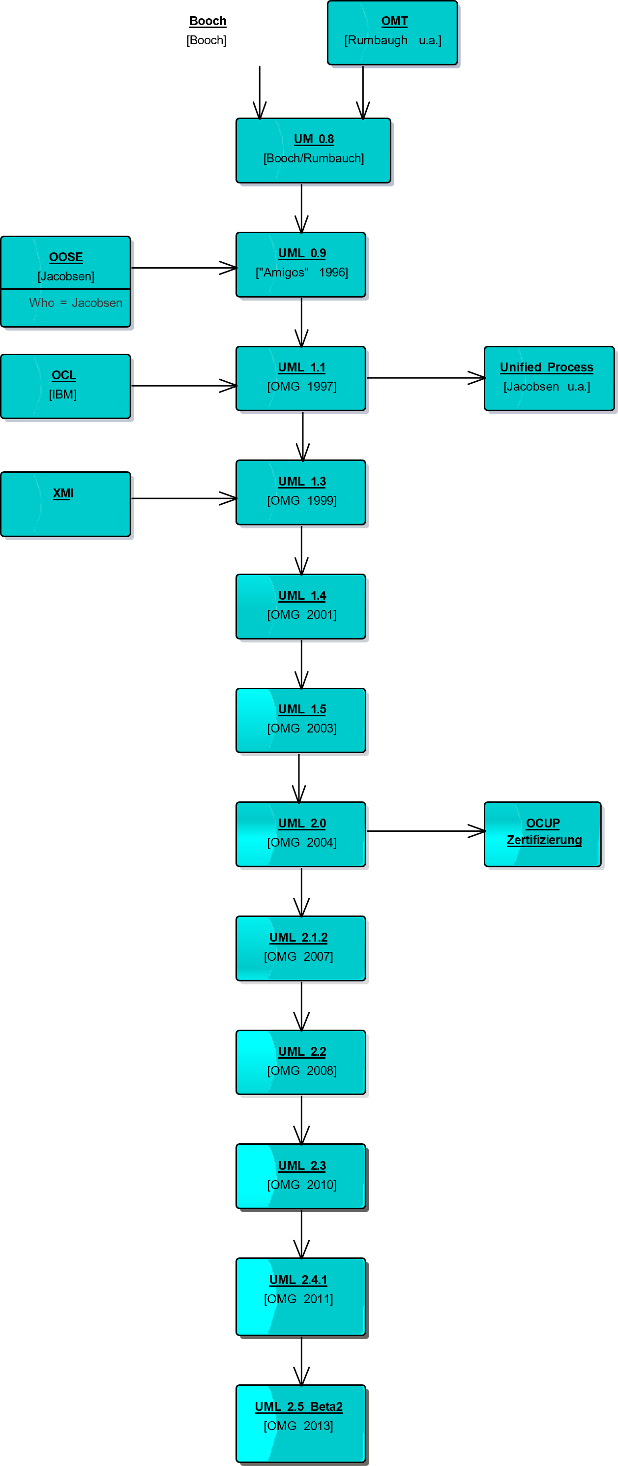
Although the idea of object-orientation is over 30 years old and the development of object-oriented programming languages dates back almost as long, the first books on object-oriented analysis and design methods did not appear until the early 1990s. The forefathers of this idea were Grady Booch, Ivar Jacobson and James Rumbaugh. Each of these three ‘veterans’ had developed his own method, which was, however, specialised and limited to certain areas of application.
In 1995, Booch and Rumbaugh began to merge their methods in the form of a common notation to create the Unified Method (UM). However, the Unified Method was soon renamed Unified Modelling Language (UML), which was also a more appropriate name because it was essentially just a standardisation of the graphical representation and semantics of the modelling elements and did not describe any methodology.
Modelling Language is basically just another paraphrase for notation. A short time later, Ivar Jacobson also joined, so that the use cases he coined were integrated. From then on, the three of them called themselves ‘Amigos’.
Because the methods of Booch, Rumbaugh and Jacobson were already very popular and had a high market share, the merger into the Unified Modelling Language (UML) formed a quasi-standard. Finally, in 1997, UML version 1.1 was submitted to the Object Management Group (OMG) for standardisation and accepted.
Versions 1.2 to 1.5 each contain a number of corrections. Version 2.0 has been adopted as a standard since 2004 and contains some significant changes and enhancements. Version 2.3 became the standard in 2010 and the current version 2.5.1. in December 2017 (source: OOSE).
UML Diagram types
UML Standard
There is no official diagram overview or categorisation in UML. While UML models and the repository behind the diagrams are defined in UML, diagrams, i.e. special views of the repository, can be defined relatively freely.
In UML, a diagram is actually more of a collection of notation elements. For example, the package diagram describes the package symbol, the merge relationship, etc. A class diagram describes the class, association, etc. Nevertheless, classes and packages can of course be shown together in a diagram.
A diagram consists of a diagram area surrounded by a rectangle and a diagram header in the top left-hand corner. The diagram header contains (optional) diagram type, (mandatory) diagram name and (optional) parameters.
The diagram type is, for example, sd for sequence diagrams or cd for class diagrams. The parameter field is important for parameterisable models.
UML version 2.5 contains 13 diagram types, which can be roughly divided into two groups. The group of structure diagrams represents static aspects of a system, the group of behaviour diagrams the dynamic parts.
UML Diagrams
Diagrams are important elements in UML. Find out about all diagram types at a glance here.
Fundamentals of behaviour modelling
Modelling behaviour is about describing processes, temporal dependencies, state changes, the processing of events and the like. UML is object-oriented, i.e. behaviour is not something that exists independently, but always relates to specific objects. The execution of a behaviour can always be traced back to an object in detail.
Every behaviour results from the actions of at least one object and leads to changes in the state of the objects involved.
In UML, behaviour is always event-oriented. The execution of behaviour is always triggered by an event. Two special events always occur: the start event and the termination event.
Behaviour can either be started directly, which is called a behaviour call event (CallBehaviorEvent), or indirectly by a trigger (TriggerEvent), for example when a point in time is reached (TimeEvent), a message is received (ReceivingEvent) or a specific value is reached or changed (ChangeEvent).
The UML provides four different types of behavioural descriptions:
A use case diagram is actually a structure diagram, because the use case diagram itself does not describe processes and behaviours, but only the structure (relationships) of use cases and actors. In many publications on UML, the use case diagram is nevertheless classified as a behavioural diagram. Its content relates to the desired functionality.
UML with Enterprise Architect
In our basic training course, you will learn how to use the Unified Modelling Language (UML) for conceptual modelling with Enterprise Architect in the best possible way using practical examples.
