Use Case Diagram
Use Case Diagrams provide a very good overview of the overall system at a high level of abstraction. They describe the functionality – the services and performances to be provided – from the user’s perspective. Each relationship between an actor (user or external system) and a use case usually leads to the definition of interaction points (interfaces) in the subsequent detailed design. It should be noted that use case diagrams themselves do not describe any behaviour or processes, but only the context between a set of use cases and the actors involved. These can be used to analyse and manage requirements. Similarly, no order of occurrence of the described activities/services is shown.
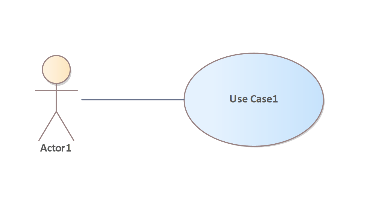
A key advantage of the Use Case Diagram is the structuring of the functional requirements – what will the system be able to do? All further descriptions can be structured hierarchically, as sub use cases or through other models ‘behind’ them. Project validation through rapid definition of the scope of tasks and a cost estimate based on this are further advantages. Use cases therefore offer a complete overview of the functions of the system to be created.
Use cases describe the goals of the users and are therefore particularly suitable for analysing functional requirements of a system that are relevant to the users of the system (stakeholders). The use case diagram consists of a few very clear elements and is ideally suited for communication between the client and contractor due to its simplicity. Both sides develop a common picture of the system, so misunderstandings about the functional scope can be avoided at an early stage.
The use case diagram is simply the graphical representation of use cases and their relationships to the environment and to each other. Important information is contained in the meta information of a use case or is specified in detail in other diagrams.
A use case includes at least: name, description (note), pre- and post-conditions and a scenario with the essential steps that are necessary to carry out the use case.
By collecting the most important information and requirements for the system in the form of use cases, the individual use case can also be used as the starting point for a test case. There should be at least one test case for each use case. All the pre- and post-conditions defined in a use case, the other qualitative requirements for the use case and the individual scenarios and their alternatives are used to derive the individual test cases.
Fig. 5: Application
The Use Case Diagram in the adjacent figure shows two use cases and the associated actors. Although the two use cases read from top to bottom suggest a sequence, this is neither given nor intended by the UML. The diagram only describes which use cases exist and who is involved. The processes and the sequence can be described in the scenario (naturally a linguistic description of the process of a use case) or as a separate use case, e.g. in activity diagrams, in state machines or in sequence diagrams.
Actors
In a Use Case Diagram, all participants (actors) of a process (use case) are visualised with the help of actors. The actor is defined as a role that is outside the system of the associated use case and interacts with the system described by its use cases. Actors can be people who operate the system or external systems that access or interact with the system. They have requirements for or an interest in the system and are accordingly interested in the results. Triggers can also occur independently of actors, e.g. time-related triggers.
An actor describes a role that can be replaced in a specific case by something tangible (e.g. the person Maria Musterfrau). For example, the Customer actor can be replaced by any person who is a customer of the bank. If the actor cannot be replaced by something concrete (concrete person), it should be labelled as an abstract. Abstract elements are written with an italicised name in UML. An abstract element cannot be described by a concrete characteristic in ‘reality’, but serves as an abstraction.
The use of an actor is sometimes too ‘general’ and can be refined by defining a UML profile. Tim Weilkiens has shown a proposal for an extension profile in the book ‘Systems Engineering with SysML/UML’. In it, actors are refined into user system, sensor, actuator, environmental influence, etc.
The Use Case Diagram in the illustration opposite shows two use cases and the associated actors. Although the two use cases, read from top to bottom, suggest a sequence, this is neither given nor intended by the UML. The diagram only describes which use cases exist and who is involved. The processes and the sequence can be described in the scenario (naturally a linguistic description of the process of a use case) or as a separate use case, e.g. in activity diagrams, in state machines or in sequence diagrams.
Fig. 6: Notation of actors
Use Case
A use case specifies a function (set of actions) that is executed by a system and leads to a result that is usually of importance to an actor or stakeholder. Use cases represent the behaviour of a system and are usually described in more detail in behavioural diagrams. Suitable use cases for a ticket system are, for example, the purchase, reservation or cancellation of tickets.
Fig. 7: Notation of use cases
Notation of use cases
The following illustration shows different forms of notation for use cases. The figure on the left is the standard notation. However, it is also permitted to write the name of the use case below the ellipsis. This has the advantage that the size of the ellipse does not have to scale with the length of the use case name. Just as actors can be displayed as rectangles with the Actor stereotype, this is also possible for use cases. Instead of the ‘Use Case’ stereotype, UML offers a display option with a use case symbol.
System (System Boundary)
The system is not a direct, logical model element of UML. System refers to the context of the use case in which the actions specified by the use case are executed. The system can, for example, be a class or a component that represents the entire application. The system is represented by one or more system frames (boundary), and the use cases – the services that the system is to provide – are drawn in the system frame.
Note: Frequently required issues are described as separate use cases and can be reused as often as required using
‘include’ relationships can be reused as often as required. Every use case that has been included by an
‘include’ relationship is ALWAYS executed when the including use case is executed.
Fig. 8: System
Relations
The use cases and actors are related to each other in a certain way. The relationships are modelled with lines. Such a connection between actor and use case means that both communicate with each other. An actor is linked to use cases by means of a simple association. This usually means that the use case can be executed by the actor. By adding more detail to the relationship, a more semantically expressive model can be created.
As with associations in the class diagram, it is also possible to specify multiplicities here. The multiplicity on the use case side indicates how often this use case may be executed simultaneously by the actor. If no specification is made, the multiplicity is always 0..1. On the actor side, the multiplicity means how many actors of the specified role must or can be involved in the use case. If no specification is made, the multiplicity is 1..1 or, in simple terms, 1.
Usually no navigation information is used. However, directed associations are permitted. They do not signify a data flow direction – which is how they are usually interpreted – but indicate the initiator of communication between the actor and the system. This describes which part is active and which is passive. If an actor navigates to a use case, then the actor is the active part and initiates the use case. In the opposite case, navigation from the use case to the actor, the actor is the passive part and is required and requested to participate by the use case.
Fig. 9: Multiplicity and active/passive actors
The example in Fig. 9 describes that a customer triggers the withdraw money use case, but only once at a time. The actor bank server is required to withdraw money (it is passive). However, the bank server can be involved in any number of withdraw money use cases at the same time, whereas the customer can only be involved once.
Use cases that cannot be called directly by an actor are often labelled with the stereotype ‘secondary’. This is not part of the UML standard, but it is common to label use cases as ‘secondary’ if they cannot be executed directly by an actor, but only make sense in the context of a ‘primary’ use case or should only be executable in its context. Primary use cases are not labelled with an additional stereotype.
Fig. 10: Sample «include» relation
In the use case diagram, the ‘include’ relationship describes that a use case always calls another use case. When exactly the included use case is to be executed cannot be described in the diagram. This is described in text form in the use case scenario or in a behaviour diagram that shows the use case in more detail.
Note: When using contains relationships, make sure that only use cases of the same abstraction level are linked. Including tempts you to delve deeper and deeper into the system to be described. A use case enter PIN, which should be included in Authenticate (include), would be too detailed. In addition, enter PIN is a poor use case because the process (workflow) behind enter PIN is too small to define a separate use case for it.
Note: Frequently needed issues are described as separate use cases and can be reused as often as required using
«include» Beziehungen beliebig oft wiederverwendet werden. Jeder Use Case, der durch eine
«include» Beziehungen eingebunden wurde, wird IMMER ausgeführt, wenn der einbindende Use Case ausgeführt wird.
Extension relation
If parts of a use case are only executed under special conditions, these parts can be modelled as separate use cases and integrated using an ‘extend’ relationship.
Fig. 11: Sample «extend» relation
The extension relationship points to the use case that is being extended and is based on the use case that describes the behaviour of the extension (see Fig. 11).
Note: Intuitively, ‘extend’ would be interpreted the other way round. However, the arrow points in the direction of the use case that is being extended ( A ‘extend’ B ). Otherwise the relationship would have to be called ‘extended by’.
The extended use case can optionally be described in more detail using an extension point (see Fig. 12). An extension point describes the event under which the extension is activated. A use case can define any number of extension points. In addition to the extension point, conditions can also be defined. If no condition is specified, the extension always takes place. An actor does not necessarily have to be linked to the extending use case. If this is the case, it can be labelled with the stereotype ‘secondary’.
The example ‘withdraw money’ shows the use case ‘withdraw cash’ in rectangular notation. The use case contains two extension points. Both extension points describe the condition under which the extension is executed. The extension relationship contains a restriction (constraint: {paper available}). The extension point must occur and the constraint must be fulfilled, only then is the extending use case executed.
As with the ‘include’ relationship, no time is specified in the diagram for the ‘extend’ relationship when the extending use case is executed. The time can also be defined in the use case scenario or in a behaviour diagram.
If a use case is extended by several use cases, a relationship between the extension point and the ‘extend’ relationship can be created by specifying an additional letter (see Fig. 12, addition (a) and (b)).
Note: When using extension relationships, it is important to ensure that only use cases of the same abstraction level are described. The extension tempts you to delve deeper and deeper into the system to be described.
Note: The behaviour of use cases can be extended using ‘extend’ relationships. If an extension point is defined, any existing condition (constraint) is checked when it occurs and the extended use case is then executed.
Fig. 12: Example ‘extend’ relationship with extension points & condition
Fig. 13: Generalisation Use Cases
Specialisation (generalisation)
A use case (or an actor) can be specialised by further use cases (or actors). For example, selling at the box office is similar to selling on the Internet except for the sales channel. It makes sense to create a general use case ‘selling’ and to accommodate the changed processing steps that arise from the different sales channels in the specialisation of this use case.
Generalisation relationships are also used to describe functionalities in a general and abstract way. The authentication use case in Figure 14 is abstract and cannot itself be executed. The two refinements fingerprint authentication and PIN code authentication are two specific variants of the general use case. Authentication can be used as a ‘placeholder’ to make it clear that customers must authenticate themselves and that one of the two variants can be selected.
The abstract authentication use case contains a general description of how authentication is carried out. The concrete use cases describe the deviation from the more general case, as described in the example of the ‘selling’ use case above.
An actor describes a role, which can be defined in any abstract way. For example, a customer of a bank can perform the use case of withdrawing money. If the bank from which money is withdrawn is the customer’s house bank, the customer should also be allowed to deposit money.
This can be described by another actor (customer of own bank). Since the customer of the customer’s own bank is also a customer, he is of course allowed to do everything that a customer is allowed to do, including withdrawing money.
This can be done by a generalisation between the actors customer and customer of own bank (customer of own bank points to the more general actor customer). The customer of one’s own bank is therefore also a customer (generalisation is also referred to as is-a relationship), so the customer of one’s own bank also inherits the relationship to the use case of withdrawing money from the customer. The customer actor, on the other hand, is not allowed to execute the deposit money use case.
Fig. 14: Generalisation of actors
Note: The generalisation always points in the direction of the more general element, hence the name
‘generalisation’. This type of connection is also referred to as an is-a relationship, as everything is ‘inherited’ from the more general element. The customer of your own bank is therefore also a customer.
Fig. 15: Notes
Descriptions and notes
UML allows detailed descriptions to be added for all use cases and actors in the form of verbal formulations. Alternatively, behavioural models can be used to add details in a structured form. Notes can be added to the diagrams to indicate key design considerations. Notes are shown with a rectangle whose top right corner is bent.
A dashed line establishes the connection between the note and the element to be explained. In order to avoid duplication between the notes appearing in the diagrams and the information in the elements, the option of quoting internal content has also been provided.
| Name/Symbol | Usage |
|---|---|
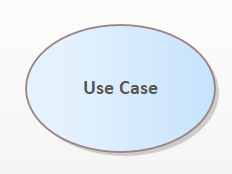 | A use case is represented by an ellipsis containing the name of the use case. The name of the use case is usually formed by a noun and a time word, which briefly and precisely describes the manipulated object and the activity performed. |
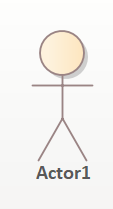 | A use case is triggered by an actor. The representation corresponds to a stick figure. You can also represent an actor in a rectangle and specify the stereotype ‘Actor’ above the name of the actor. |
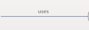 | An actor has a relationship to the use case when the use case triggers it. This relationship is represented by a connecting line between the use case and the actor. |
 | If a use case is extended by a second one under a certain condition, this relationship is indicated by connecting the use cases with an arrow that is labelled with the ‘extend’ stereotype. The arrowhead points to the use case that is being extended. |
 | If a use case is contained in a second use case, i.e. it is an integral part of it, both use cases are connected with an arrow labelled with the stereotype ‘include’. The arrowhead points to the contained use case. |
 | This relationship can be modelled between actors and between use cases and means that a use case or an actor is specialised. The arrowhead points to the actor or use case that is being specialised. |
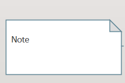 | Notes are diagram elements that are attached to other modelling elements. They contain information for understanding the model and are connected to the element by a broken connecting line. |
Example
A customer wants to withdraw money from an ATM using an ATM card. The Customer actor characterises the role of the customer and is the generalisation for the Customer actor role of the own bank’s customer. The specialised customer of own bank actor can execute the authenticate use case via the customer role, which runs equally for both customer types.
This use case contains the account and PIN check use case, in which the customer’s authorisation to use the card is checked. If an incorrect PIN has been entered several times (constraint: {3x incorrectly logged in}), the card is cancelled. To model this, the authenticate use case is extended with the revoke card use case. This is only processed under the condition that the customer has failed to identify themselves several times.
The own bank’s customer actor communicates directly (not via the customer role) with the deposit money use case. The customer, on the other hand, has no relationship with the deposit money use case and is therefore not allowed to do so.
Fig. 16: Sample Use Case Diagram

