Sequence Diagram
The Sequence Diagram focusses on the chronological sequence of the messages. The order of the messages corresponds to their horizontal position in the diagram. It is determined when an object is created and when messages are sent to which object.
The objects involved are represented by a rectangle and a vertical dashed line. Both together are called the lifeline. Messages are represented by arrows between the lifelines. Time runs from top to bottom. This emphasises the progression of the messages over time.
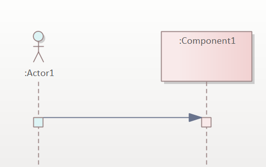
Fig. 53: Simple example of a Sequence Diagram
The Sequence Diagram in the illustration shows an interaction between three objects. It should be noted that the entire diagram represents an interaction and that an interaction is not just a single message exchange.
The header of the lifeline contains the (optional) element name with the associated class in the usual declaration notation: name: typ.
Execution focus
If messages are exchanged between lifelines, a behaviour must also be executed in the associated elements. This is represented by the elongated rectangles on the lifeline. The rectangles represent the so-called execution focus (ExecutionOccurence). The start and end of the execution focus are defined by so-called event occurrences. Put simply, the sending and receiving of messages determines the start and end of the execution focus.
Message types
The transmission of a message is noted with arrows. The messages are labelled with the names of the associated operations. UML recognises different types of messages, which are represented by different arrow notations. The following list shows the different message types and associated notation forms.
- Synchronous messages are characterised by a filled arrowhead. Synchronous means that the caller waits until the called behaviour has been completed. The reply message to a synchronous call is shown with a dashed line and an open arrowhead.
- Asynchronous messages have an open Asynchronous means that the caller does not wait, but continues immediately after the call. Accordingly, there are no response arrows for asynchronous calls.
- Lost messages have an open arrowhead pointing to a filled circle. The circle is not connected to a lifeline. In the case of a lost message, the sender of the message is known, but not the recipient.
- Found messages have an open arrowhead pointing to a filled circle. The circle is not connected to a lifeline. With a found message, the recipient of the message is known, but not the sender.
- A message that creates a new copy is marked with a line and an open arrowhead. The lifeline associated with the copy only starts at this point in the diagram, i.e. the arrow points to the head of the lifeline.
The repeated sending of the message is modelled by prefixing the * character. In this case, the message is preceded by the * character.
The message is noted on the message arrows. The syntax is [attribute =] name [(arguments)] [: return value]
Fig. 54: Notation forms of the different message types
Where
- attribute can be a local variable of the interaction or a copy of a lifeline. The attribute assignment is only used for synchronous messages with return value
- name is the name of the message to be called or the name of the signal to be sent. Sending a signal is always asynchronous.
- arguments is a comma-separated list of the parameter values passed to the message.
If an object is created by sending a message (e.g. by calling the new method), the lifeline of the object only begins at this position. The resolution of an object is represented by a cross on the lifeline.
Symbols
The following table contains the symbols of the sequence diagrams.
| Name/Symbol | Usage |
|---|---|
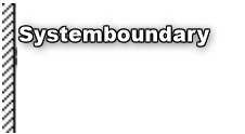 | The system boundary isolates the programme section under consideration from the rest of the programme. It usually serves as the starting point for the triggering method call. The programme flow is not always triggered by an object outside the area under consideration, which means that no system boundary needs to be drawn in this case. |
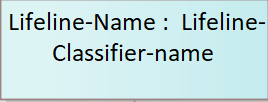 | An object is shown with a rectangle containing its name. The underlining of the name can be omitted here, as no confusion with the class name can occur. Classes are not shown in this diagram. The objects are displayed next to each other along the top edge of the sheet. |
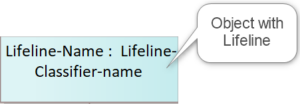 | Each object lies on a vertical line, the lifeline. The lifespan of the object increases in the direction of the bottom edge of the sheet. For objects that already exist at the start of the programme section, the object symbols are drawn at the top edge of the sheet. For objects that are newly created within the programme section, the symbol is drawn at the height of the method call that creates the object. |
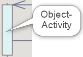 | If an object is involved in a method call, it becomes active. The lifeline thickens. If an object calls its own method, the lifeline thickens again. These activities are not always drawn. |
| If an object calls a method of another object, this is symbolised by a continuous arrow pointing to the object whose method is being called. The method name is written next to this symbol. The parameter list can be added to this name in brackets. | |
| In principle, only the method calls are drawn in the sequence diagram. If you still want to draw the return of the methods, you can do this with an arrow and a broken line. |
|
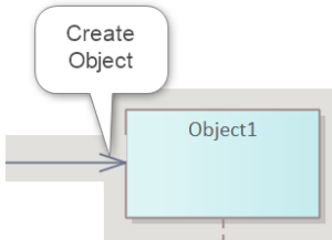 | If a method creates an object, the arrow of the method ends at the rectangular symbol of the object. The lifeline starts at this symbol. |
Example
In a ticket system for a theatre, tickets are sold on a website from the seating plan. The seating plan manages the seats for an event.
If a seat is selected by a visitor, the relevant object aSeat calls the ‘buy’ method of the object aOrder and passes a reference to itself in the parameter.
The object of the order class calls the ‘isFree’ method of the seating plan class to check whether the seat passed in the parameter is still free. If the seat is still free, the seating plan object calls its own ‘reserve’ method. This initially reserves the seat.
Fig. 55: Example of a Sequence Diagram
Once this has been done, the invoice for the seat is created. To do this, the seating plan object calls the ‘book’ method with the selected seat as a parameter. The ‘book’ method belongs to the aSale object. This represents a list of invoice items, which is not modelled here.
After the invoice items have been compiled by the sales object, it calls the ‘createInvoice’ method of the aOrder object. To inform the Internet visitor of the success of their purchase, the order object calls the ‘confirmed’ method of the place class. The visitor confirms the order and the ‘confirmed’ method returns with the value ‘true’. The order is completed.

