Deployment Diagram
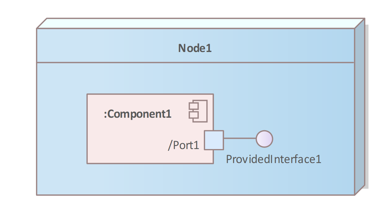
Dependencies between nodes, the nodes themselves, their contents and communications are shown in distribution diagrams. A node is a physical unit that has storage space and computing power (e.g. a PC) on which components run. The nodes are drawn as cuboids.
Components or runtime objects (processes) can be entered in the cuboids. Instead of cuboids, images can also be used to represent the nodes graphically. Distribution diagrams show which components and objects are running on which nodes (computers, processes), i.e. how they are configured and which communication relationships exist.
Symbols
The following table contains the symbols of the deployment diagrams.
| Name/Symbol | Usage |
|---|---|
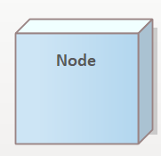 | A node is represented by a cuboid. The label that is specified within the cuboid is given the name of the node, e.g. a computer name, a client name or a process name. |
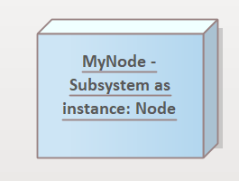 | If an application is executed in memory on a node, this application is modelled as a node instance. The labelling in the cuboid is underlined to distinguish it from the node symbol. This symbol is inserted into the node symbol on which the sub-process is running. |
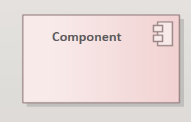 | A component is smaller in size than a subsystem, but performs the tasks of the application for a defined application area. The component symbol is inserted into the node symbol on which the component was installed. |
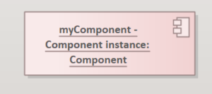 | The component instance is a collective term for the objects whose classes belong to the data structure of the component and are instantiated by it. The symbol does not differ from the component symbol. In contrast to the component symbol, the name of the instance is underlined. The symbol is inserted into the component symbol whose instance it represents. |
 | The relationships between the nodes are shown with a solid line connecting the nodes. |
Example
With a ticket system for cinemas, ticket data can be accessed from different applications. The data is stored on a central server that is networked with other PCs and connected to the Internet.
A component for administering the database is installed on the server. The Interbase database server is set up on the server.
Fig. 61: Sample Deployment Diagram
- Sales at the box office are handled by a PC in the box office hall. A client application has been developed that has been specially adapted to the requirements of sales at the box office so that it can access the data very quickly.
- The system administrator has a PC for his tasks, e.g. in the accounts department. He also has a client application that enables him to create and analyse events.
- The advance booking office is operated with its own client application, which is connected to the server via the Internet.
- The Internet customer calls up data from the ticket system via the Internet from a PC. This requires a client application of the ticket system customised for these customers.

