Activity Diagram
Activity diagrams can be used to describe time sequences. This makes it possible to describe processes, workflows and algorithms at different levels of abstraction. Activity diagrams are often used to describe use cases in more detail. Use cases can also be described using natural language, so-called scenarios, but the overview is only retained for very simple processes.
With activity diagrams, on the other hand, it is possible to visualise even very complex processes with many exceptions, variants, jumps and repetitions in a clear and comprehensible way. In practice, it is now common practice to break down textual scenarios into diagrams in order to have the statements they contain available as addressable elements in the model. In addition to activity diagrams, other behavioural diagrams, such as the state diagram, sequence diagram, etc., can also be used to describe use cases.
Note: The semantics of the individual model elements sometimes differ considerably from the model elements in UML 1.x despite having the same names.
The activity element from UML 1.x has given way to action, while an entire activity model is now called activity. Some notes on the UML versions can be found at the end of the chapter on activity diagrams.
Activity
The activity describes the sequence of actions. It is represented by a rectangle with rounded corners. The rectangle contains the nodes and edges of the activity. The nodes of the activity are usually actions. There are a number of different actions. The ‘normal’ action is used most frequently. Two other important actions are the CallBahaviourAction and CallOperationAction to call a behaviour within an activity that is defined elsewhere. However, it is also permitted to draw further activities within an activity – sub-structuring.
Like every behaviour in UML, an activity can also have parameters. Incoming or outgoing objects of an activity are referred to as parameters of the activity. These objects are placed on the rectangle of the activity and optionally listed below the name of the activity with a type specification.
The following example shows an activity for the production of six-packs. The activity has two parameters: an input parameter Produced bottles in [empty] state and an output parameter New six-pack. The exact declaration of the activity parameters can be found at the top left directly under the name of the activity.
Fig. 17: Sample activity ‘Production of six-packs’
There are various types of nodes and edges in the activity.
The rectangles with rounded corners within the activity are actions. The small rectangles on the actions are so-called pins. They provide the incoming and outgoing objects for the actions.
Token concept for activity diagrams
Until UML 1.x, activity diagrams were defined as a mixture of state diagrams, Petri nets and event diagrams, which led to all kinds of theoretical and practical problems.
Since UML 2.x, activity diagrams have been based on token semantics borrowed from Petri nets, which have been used to create precise rules for the flow of processes and objects, including parallelisation and merging. A token corresponds to exactly one process thread that can be created and destroyed. The token represents either the progress of the flow or the data flow. The more formal specification of the semantics of the activity diagrams now makes it possible to carry out automatic verification by simulating activity diagrams.
The following terms have changed as a result of the revision of the UML activity diagram:
- The individual elementary, indivisible steps in a process are no longer called activities, but actions.
- A set of steps, i.e. ultimately a flowchart or sub-flow, is now called an activity.
- Whereas up to UML 1.x every incoming transition started a flow step, there is now an implicit synchronisation, i.e. all incoming object and control flows must be present for the action to start.
- Similarly, an action node is only exited when all outgoing edges can fire. In UML 1.x it was the other way round, if several outgoing edges (previously called transitions) were noted, it had to be ensured via corresponding conditions that only one edge could fire.
- There are some new elements:
- Activities can have object nodes as input and output parameters.
- Pre- and post-conditions can be defined for activities
- Start and end activities are now called start node and end node
Connections
The connections between actions are divided into control flow and object flow edges (ControlFlow and ObjectFlow). In the notation, both edges are the same: a solid line with an open arrowhead.
Object flow edges are explicitly differentiated by being drawn between object pins or activity nodes (small rectangle at action or activity), leading to or from a datastore, central buffer node or object.
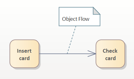
Fig. 18: Control flow object flow (a)
A control flow connects actions and activities. After card reading is complete, the imaginary token flows along the control flow if the check card is ready to be activated.
With an object flow, data is also transmitted in addition to the control. If several object tokens arrive, these are passed on according to FIFO by default. An object can also be used as an alternative to pin notation.
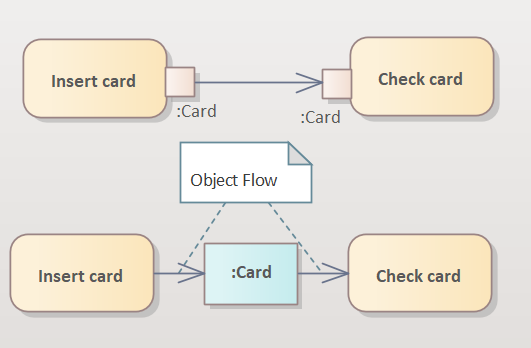
Fig. 18: Control flow object flow (b)
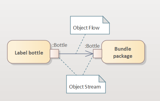
Fig. 18: Control flow Object flow (c)
Object streams are a special case of object flows. This is a continuous flow of data (objects). Comparable to a conveyor belt on which bottles are constantly being filled.
Object streams and control streams can also be split. A central buffer node or a datastore can be used to store data temporarily or permanently
Goods can be temporarily stored in the shopping basket (Central Buffer Node) and retrieved later. If the process is terminated beforehand, temporarily stored data is destroyed – in contrast to the data store.
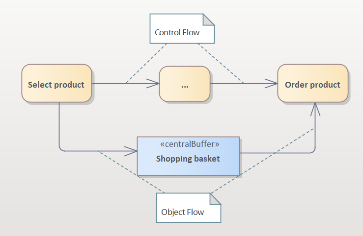
Fig. 18: Control flow Object flow (d)
Branching
A branching of the process is achieved using a diamond symbol (decision). A decision can have any number of outgoing edges (usually at least 2). If there are several outgoing edges, this is interpreted as a switch. Alternatively, a switch can be expressed by several consecutive decisions, but this is a poor modelling style. It should be noted that each outgoing edge of a decision has a guard condition.
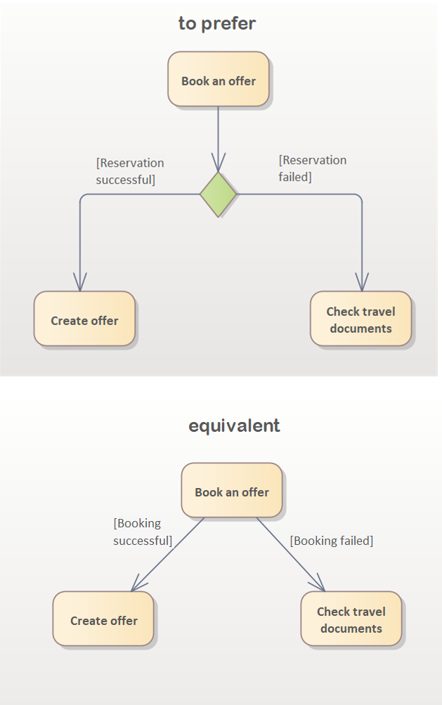
Fig. 19 Explicit vs. implicit decision
Note: Guard conditions must be complete
(x< 0 and x > 0; error at x==0) and must not overlap (x <=0 and x >= 0; error at x==0).
As an alternative to the decision, the outgoing edges with their guard conditions can lead directly from an action/action.
Caution: However, multiple unlabelled outputs from an action/activity mean splitting (parallelisation).
As this can easily be confused, the diamond symbol for branching (decision) is usually set, which makes it clear that only a single output is selected (disjoint).
Merging
A decision is used to select an alternative path in the process. If there is a need to define loops, it is necessary to use a merge element.
If a merge element is omitted and the returning edge is routed directly to an action/activity, this implies the merging of two concurrent processes (implicit join).
If the returning edge is routed directly to Select appointment, a token must be present at each edge. This will never happen in this example and leads to a blocked process (dead lock).
Two incoming edges in an action/activity are not prohibited according to UML (see Fig. 20), but the implicit join semantics must be taken into account. To avoid incorrect interpretations, implicit UML semantics should be avoided altogether.
Fig. 20: Merge
Splitting (parallelisation) and synchronisation
A splitting node (fork node) is used to parallelise a process flow in order to model concurrent processes. Concurrency means temporally independent, but does not necessarily mean simultaneous. Creating travel documents and reserving an offer (Fig. 21) can, but do not have to, be carried out at the same time. A fork may also have more than two outgoing edges.
With the fork node, each incoming token is duplicated and a token begins to run on each outgoing edge. If a token cannot be passed on at an outgoing edge, it is temporarily stored in a FIFO list until the subsequent action/activity can pick up this token. This is an exception in UML activity diagrams, as no tokens are usually left at ‘pseudo’ nodes.
Concurrent processes can be merged using synchronisation (join node). To do this, a token (control or object token) must be present at each incoming edge. After merging, all adjacent control tokens and identical object tokens are merged into one. In contrast, all adjacent object tokens are passed on! Only identical object tokens are merged and only passed on once.
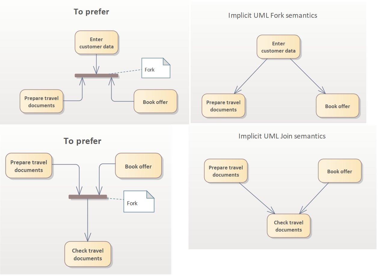
Fig. 21: Splitting and Synchronisation
Fig. 22: Join Specification
The join node has implicit and semantics. If only a selection of concurrent processes needs to be completed in order to continue the process synchronously, the UML offers the Join Specification (JoinSpec). This makes it possible to define a condition that describes the join. In the example, a token must be present at edge a and b or a and c. The film must be selected in any case, it does not matter how it is paid for.
Nesting of activity diagrams
Activities usually consist of actions that describe the individual steps of an activity. This is comparable to an operation/function in a programming language and the individual instructions in the operation. Just as an operation can call other operations, this possibility also exists for actions in activities.
Nesting helps a) to get by with the usual A4 format (even over several pages) and b) to structure the contents in such a way that they have a level of detail suitable for the respective releaser responsible.
An activity is called up using a call behaviour action.
If parts of a use case are only executed under special conditions, these parts can be modelled as separate use cases and integrated using an ‘extend’ relationship.
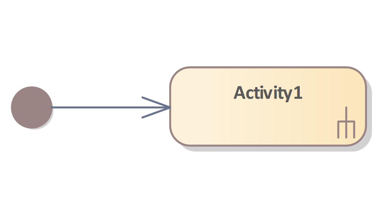
Call behaviour actions can be distinguished graphically from other actions by a fork symbol in the bottom right-hand corner.
In Fig. 23, the withdraw money activity calls the Spend card activity several times. Release card can in turn be described by any action.
Note: The problem of duplicated actions/activities can be avoided with Call Behaviour Actions. The trick is to define an activity that can be called any number of times by Call Behaviour Actions.
It should be noted that only activities can be called by call behaviour actions.
Fig. 23: Calling an activity using an action
Call operation actions are similar to call behaviour actions, but they do not call a behaviour (activity), but instead directly call operations that are defined elsewhere (e.g. operations of a class). The error message action in Fig. 23, for example, calls the error message output() operation of the ATM class.
Call operation actions can be used to explicitly link activity diagrams and structure diagrams, such as the class diagram, and thus define where a certain behaviour is implemented. On the one hand, this is required by quality systems (SPICE, CMMI, …), on the other hand, the low effort required to create the reference dramatically reduces the effort required for subsequent change requests.
Fig. 24: Structured activities
It is possible to structure elements in Enterprise Architect. A structured (composite) element has a link to a diagram in which further information is defined. Graphically, linked elements are displayed in the bottom right-hand corner using glasses/chains.
This option is not defined in the UML specification, but offers a good way of structuring diagrams.
With this cascading of diagrams, you can maintain an overview even with complex processes. This subdivision into sub/detail models can be helpful and also necessary:
- to ensure sufficient subdivision to be able to adhere to the standard paper format and
- to create detailed breakdowns that are integrated into various documents and approved by different responsible parties.
Responsibility areas (swimlanes)
Individual actions in the activity diagram are normally carried out by a responsible actor. In order to be able to visualise the assignment of individual actions to the actors in a diagram, it is possible to introduce so-called swimlanes (areas of responsibility).
These vertical or horizontal lanes symbolise the actor and place the activities in the actor’s area of responsibility by graphically assigning the individual actions to a lane. Partitions can also be used as an alternative to swimlanes. Partitions look very similar to swimlanes, but are part of the model and not just drawn in the diagram. Fig. 25 shows the use of partitions.
Fig. 25
Asynchronous processes
Activities and actions are linked by control flows and object flows. The processes defined in this way are ‘synchronous’, i.e. it is determined which subsequent steps are possible; alternatives are also modelled directly using Decision.
By using signals (Send Signal Action, Receive Signal Action and Timer Action), it is possible to disconnect two or more processes. A send signal sends a broadcast signal. All receive signals for which this signal is intended become active. For better readability, dependencies can be defined using dependency edges from the receive signal to the send signal element.
Figure 25 shows that the order pizza action (a Send signal action) is executed and the signal for baking the pizza in the pizzeria is picked up by the receive order action (a Receive signal action).
Note: Receive signal actions do not necessarily need an incoming edge. The rule states that all activities/actions that do not have an incoming edge are assigned a token.
In the case of interruption areas, signal actions behave differently and only become active as soon as the interruption area is entered.
Fig. 26: Interruptible activity region
Interruptible activity region
The interruptable activity region defines a special area of a process. If the interruptible region is entered, the executed process can be interrupted at any time and an alternative path can be selected.
The interrupt area can be interrupted by the arrival of a signal (Receive Signal) or by the expiry of a time event (Time Event). An interruption of the process is defined by an interrupt arrow (Interrupt Flow).
If a control/object flow edge leads into the interruption area, the area becomes active and therefore also the Time Event Actions and Receive Signal Actions. If a control/object flow edge leads out of the interruption area again, the interruption area is properly exited and thus becomes inactive again.
As long as the interruption area is active, it can be exited via interruption arrows at any point. Any activities/actions being carried out are stopped. The UML specification does not contain a description of how activities/actions that have already been started are handled if they are interrupted. A best practice interpretation is that an undo (rollback) of the partially executed actions/activities is performed. Note: The interrupt flow must point from an element in the interrupt region to an element outside the region.
In the example above, the interrupt region is entered after a pizza order has been placed. While waiting for the pizza, the watching TV activity is executed. As watching TV has no outgoing edge, the process would stop here. The interruption area, and therefore also the watching TV activity, is interrupted as soon as the pizza is delivered or the wait is longer than one hour.
| Name/Symbol | Usage |
|---|---|
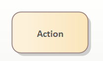 | The action symbol consists of a rectangle with rounded corners. By definition, an action is a single step that cannot be subdivided and cannot be interrupted by external influences. |
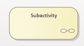 | The symbol of the structured activity is displayed with the symbol of the activity, with a spectacles/chain symbol in the bottom right-hand area. This element links to another diagram. Not part of the UML standard, but a valuable structuring construct. |
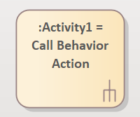 | Eine Call Behavior Action erlaubt das Aufrufen von beliebigen Verhalten (Aktivitäten) aus einem bestehenden Prozess. Damit kann die redundante Definition von Aktivitäten/Aktionen verhindert werden. |
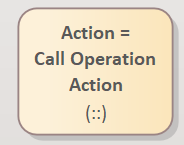 | A call operation action calls a specific behaviour of a structure element, e.g. the operation of a class. Element name and behaviour name are separated by ‘::’. ([element name]::[behaviour name]) |
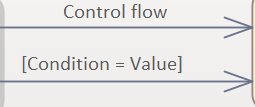 | Two actions are connected with an arrow when the activity flow changes from one action/activity to the next. The arrowhead points in the direction of the process flow. The arrow can be labelled with a condition if the process flow only takes place for this condition. This is the case if several transitions emerge from an activity or the flow is divided by a diamond (decision). |
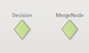 | The diamond symbol (Decision) can be used to branch or merge the process flow. If one edge comes in and several go out, this is a branching (decision); if several edges come in and one goes out, this is a merging. No labelling is usually used for a path merge. |
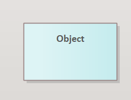 | If data is generated and used in a process, it can be represented as objects (instances of classes). The object can be specified without a type (as in the illustration on the left). For typed objects, the type name appears after the object name. The notation changes to: Object-Name:Type-Name |
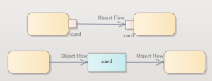 | The object flow describes the transfer of control from one activity/action to the next and transfers data (objects) in addition to control. The starting point and end point of the object flow is usually an object. This can be an ObjectNode (small square of activity/action), an object (instance of a class), a Central Buffer Node (transient buffer node) or a Datastore (persistent buffer node). Like instances of a class, ObjectNodes can have a type (:bottle) and also define their state ([filled]). |
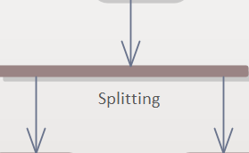 | Splitting (fork) allows the process flow to be divided into several concurrent process flows. When forking, the incoming token (control or data token) is duplicated. Each outgoing edge receives its own token. |
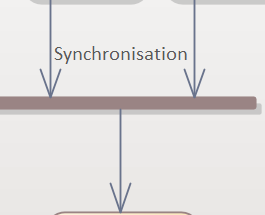 | Synchronisation (join) can be used to merge concurrent process flows. This involves synchronisation, i.e. processing is stopped until all partial flows (tokens) have arrived at the synchronisation element. The AND semantics of the join can be redefined using join specifications (see Fig. 22). |
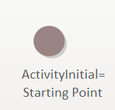 | The starting point is the starting point of the process. If there are several starting points, the affected branches of the process are started in parallel. If there is no starting point, all nodes that have no incoming edges are interpreted as starting points. For a better understanding, care should be taken to define one starting point per process. |
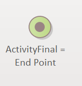 | After all actions of the activity have been processed, the process flow of this activity ends. This point is represented by the end point. An activity diagram may contain any number of end points (Activity Final); it can be omitted for endlessly running processes. By using several endpoints, the termination of the process at different points in the process can be better visualised. Caution: If endpoints are used within nested activities, the endpoint does not terminate the entire process, but only all tokens that are running in the sub-process. |
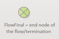 | Cancellation, Flow Final means that a token that reaches this symbol is destroyed. The process branch is cancelled here. If there are other tokens, the entire process continues to run, but if it is the last token, the entire process is terminated. |
 | If you want to model areas of responsibility in the process flow, e.g. actions/activities that belong to different packages/components/actuators, you can model the areas of responsibility with vertical or horizontal lines. The name of the area that lies between two lines is labelled with the name of the responsible element in the upper area. |
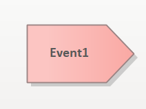 | A send signal is an action that is used to send asynchronous messages to other processes during the execution of a process. |
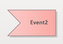 | A receive signal is an action that waits for a signal (event). Once the signal arrives, the action is executed and the flow continues. Receive events are used to model asynchrony. If the receive event has no incoming edges and the element containing the receive event is active, it is ‘ready to fire’. |
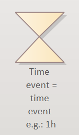 | A time event periodically generates an output (token). The output triggers further actions and can also be used in conjunction with Interruptable Activity Regions. If the time event has no incoming edges and the element containing the time event is active, it is ‘ready to fire’. |
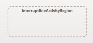 | An interruptable activity region is an area that can be exited by events (receive events, time events). All currently executed actions are interrupted and the alternative path is continued. |
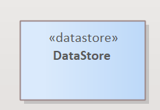 | A datastore is a persistent buffer node. It is used to store data from object flows. This can be used to express that existing data is accessed in a process or that new data is stored persistently. |
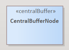 | A central buffer node is a transient buffer node. It behaves like a datastore, with the difference that stored data is deleted after the end of the activity using Activity Final. It therefore has the semantics of a local variable of an operation in OO programming languages. |
 | An interrupt flow is used to leave an interruptable activity region. |
Example
The following example describes the process for preparing a celebration. For reasons of clarity, the description has been modelled in several diagrams.
Fig. 27: Example 1 – process of organising a celebration
Fig. 27: Example 2 – process of organising a celebration
The illustration above describes three activities that are carried out one after the other (shopping, cooking, celebrating). The individual shopping actions to be performed are listed in the Shopping activity.
An object flow with the purchased good(s) flows from the shopping activity into the Cooking activity.
The types (goods, food) of the objects (object nodes) are modelled as classes and can therefore also be described in more detail.
It can be seen that cooking receives goods as input and passes on food. Cooking is modelled in a separate diagram. The cooking process begins with concurrent processes. While cooking, a song is also sung.
The concurrent process singing a song ends with a flow final. This means that when the action (singing the song) is finished, this branch of the process ‘dies’.
The second concurrent process begins with the preparation of the goods and the subsequent preparation of the goods. Goods flow into the activity of preparing goods and food flows out again. This is where goods become food. If the food is inedible, it is disposed of and a pizza is ordered.
Ordering the pizza is a Send Signal Action and is picked up by receive order (Receive Signal Action). This signal triggers the start of another independent process, the baking of the pizza.
After the pizza has been ordered, the watching TV activity is executed. An interruptable activity region is entered in the process. When the region is entered, the Receive Signal Action and Time Event Action contained in the interruptible region become active, i.e. the timer starts to run and the Receive Signal Action is ready to receive signals. Note: If the process flow is not in the interruption area, any incoming signals are discarded.
If we are in the interruption area and the signal deliver pizza (Send Signal Action) arrives, we leave the interruption area and watching TV is interrupted. In the next step, the pizza is paid for and the process flow is merged (merge node after the decision node).
Alternatively, if the pizza does not arrive within an hour, the timer runs out, the interruption area is left and a sandwich is cancelled as an alternative. The food is then brought together again.
Once the food has been placed on the plate, the cooking activity is completed.
The Send Signal Action Order Pizza starts another process asynchronously. This process is created in a separate diagram, making the model easier to read.
The Send and Receive Signal Action order pizza and pizza service rings describes who responds to the signals sent.
The Bake Pizza activity can also be refined by linking to a diagram that describes the Bake Pizza process in more detail.

