Communication Diagram
The Communication Diagram corresponds to the UML 1.x Collaboration Diagram. It has been renamed as the name Collaboration Diagram is misleading. There is also the model element Collaboration in UML, but this has nothing to do with Collaboration Diagrams.
The communication diagram represents the facts of a Sequence Diagram from a different perspective. In this diagram, special attention is paid to the collaboration between the objects. For this purpose, selected messages are used to show the chronological sequence of communication between the objects. It therefore summarises the statements of the sequence diagram in a more compact form.

Fig. 56: Example communication diagram ‘Identify authorised user’
The illustration clearly demonstrates that the communication diagram emphasises the relations between the participants and not the chronological sequence of the message exchange like the sequence diagram.
The graphical representation consists of a rectangle containing the object name and the associated class. A colon separates the two names. The objects are connected with association lines. A small arrow indicates the direction of the message from the sender to the recipient. If arguments are passed with the message, these are listed. Possible return values can also be in the form
response := message name (parameter list)
can also be specified.
In order to model the time sequence, the messages are given numbers. Further messages can be triggered by a message. They are given sub-numbers of the triggering message (e.g. 1.2).
If a message is triggered several times, this iteration can be modelled using a * character in front of the message name.
Objects that are created within the scenario shown can be labelled with the stereotype new. Objects that are destroyed within the scenario shown are labelled with the destroy stereotype. Objects that are created and destroyed within the scenario are given the stereotype transient.
Symbols
The following table contains the symbols of the communication diagrams.
| Symbol/Name | Usage |
|---|---|
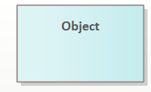
 | The rectangle is the symbol of an object and contains the object name. As there is no risk of confusion with classes, the name does not need to be underlined. |
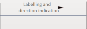
 | If two objects communicate with each other via a method call, this connection is shown with a continuous line that connects both objects. |
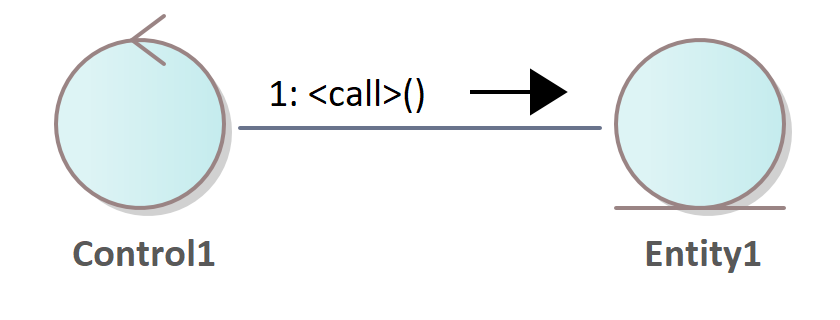
 | In addition to the connecting line, the object to which the method belongs is indicated by an arrow after the method name. The tip of the arrow points to this object. |
 | The line is labelled with the method name and the parameter list. A numbering is displayed before the method name to indicate the chronological order of the method calls and is separated from it by a colon. In a condition, you can specify the numbers of the methods that have already been processed as a prerequisite. The * character in front of the method name indicates a repetition of the method. You can specify the condition for the repetition after the * character. |
Example
The example models the purchase of a ticket via the Internet. The Internet customer selects a seat on the website of a theatre and calls up the Select method. The interaction is started. The seat object calls the buy method of the order object and passes a reference to itself in the parameter. The order object calls the IsFree method of the seating plan object.
This method calls the reserve method on the one hand and the book method on the other. They therefore only differ in the sub-number. The room plan object calls the book method of the sales object. This object calls the createInvoice method of the order object and transfers the invoice item of the booked seat.
Once the invoice has been created by the Order object, the Internet customer is notified of the successful booking. To do this, the confirm method is called, which requests and returns the customer’s confirmation.
Fig. 57: Example communication diagram ‘Ticket purchase via the Internet’
Sequence Diagrams vs. Communication Diagrams
Sequence and Communication Diagrams are very similar and can also be merged in some UML tools. The focus of the Sequence Diagram is on the temporal aspect, whereas the Communication Diagram focuses on the relations between the objects. The biggest advantage of sequence diagrams and at the same time the biggest disadvantage of communication diagrams is the clearly visible chronological sequence, which can in principle also be visualised in communication diagrams using a numbering scheme, but is less clearly visible.
On the other hand, the order of execution does not have to be defined immediately when creating the sequence diagrams, which sometimes makes the creation of Sequence Diagrams a little tricky. On the other hand, the sequence is difficult to read in a comprehensive Communication Diagram; the reader has to search to find out whether, for example, 1.1 is followed by 2, 1.2 or even 1.1.1.

